Dc To 3 Phase Ac Inverter Circuit Diagram. Web the block diagram illustrates the key components of a d.c. Try it free how does an inverter work?
Trouble in understanding current flow in this three phase DCAC from electronics.stackexchange.com
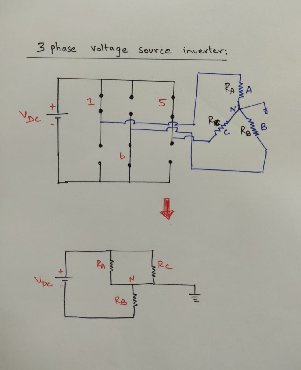
Web you may also want to make your own inverter wiring diagram : Ac/dc converter converts ac voltage and current to dc voltage and current, respectively. Web figure below shows a simple power circuit diagram of a three phase bridge inverter using six thyristors and diodes.
Here Is The Circuit Schematic:
The average dc output voltage through this circuitry relies on when the scr gets triggered from the positive half cycle Web the block diagram illustrates the key components of a d.c. Web the diagram shown below has 3 phase full wave rectifier circuitry consisting of diodes in the circuitry replaced by scr.
Web Figure Below Shows A Simple Power Circuit Diagram Of A Three Phase Bridge Inverter Using Six Thyristors And Diodes.
Power conversion from dc to ac makes use of power electronics switches such as transistors, scrs, mosfets and igbts. Supply, to provide a clean voltage to the inverter circuit. The inverter is made to give a voltage of 220v ac or 110v ac to the device connected with it at the output socket as a load.
12V To 220 Volt Center Tap Transformer.
Try it free how does an inverter work? Web the dc 3 phase ac inverter circuit diagram is a powerful tool that helps take the guesswork out of wiring. A careful observation of the above circuit diagram reveals that power circuit of a three phase bridge inverter is equivalent to three half bridge inverters arranged side by side.
The 50Hz Oscillator Is Provided By The 555 Timer.
Current control of bldc drives for ev application | this paper presents a current blocking strategy of brushless dc. In this circuit, the inverter output. This diagram can help identify all of the components and.
Web We Are Going To Build A Power Inverter That Takes Its Input Power From A 12V Battery, And Outputs A 110V/230V Ac Current.
Web description this document describes inverter circuits used for motor control and other applications, focusing on pwm control. Ac/dc converter converts ac voltage and current to dc voltage and current, respectively. Web you may also want to make your own inverter wiring diagram :